Although this is not as indepth as some would prefer it will save you some time when adjusting valve lash with either solid lifters or hydraulic with adjustable pushrods and or adjustable rocker arms.
Disconnect the Battery
Remove all spark plugs ( so engine will turn easier ).
If you are going from stock to adjustable pushrods/rocker arms removal of the intake manifold is required so a visual check of the lifter cup is possible.
If you have a factory harmonic balancer you will need to make a visable mark at 180 degrees from TDC on the balancer which is half the diameter ( 1 full rotation is 360 degrees ).
A 1/2" drive breaker bar and a 1-1/8" deepwell socket attached to the balancer bolt is a simple way to rotate the engine for this proceedure, if you use the starter to bump the engine it is easy to overshoot each nessecary stopping point which will be charted below.
This Chart represents which valves to adjust from a starting position of #1 TDC Firing Position and adjusting the first set and then rotating the crankshaft clockwise to the next point and adjusting the valves which are listed next and so on.
Crankshaft Position #1 TDC Firing Rotate engine180* clockwise (from front) to #4 TDC Firing Rotate 180* clockwise to #6 TDC Firing Rotate 180* clockwise to #7 TDC Firing |
Intake #2 and #7 #1 and #8 #3 and #4 #5 and #6 |
Exhaust #4 and #8 #3 and #6 #5 and #7 #1 and #2 |

[Under Construction]
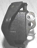
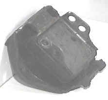
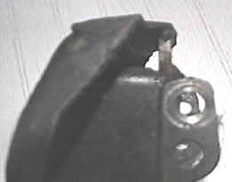
Anyone wanting to tye the engine of their big block or even the small blocks, heck it might even work on the V-6, to the frame without using tiedowns, chains, midplates or using a store bought solid motor mount that does not fit properly. I spent days trying to figure out how I was going to tye the engine down with out using up valuable engine bay space. Well heres a solution that worked for me.
Tools required.
1. Welder, die grinder or dremmel with fine metal shaving bits, bench
grinder, hack saw and a vise.
2. I would also recommend using a fresh set of motor mounts if available.
Take the stock motor mounts and make sure they are clean and free of oil or grease.
You will need about 6 inch long piece of 1/4 inch x 1inch steel bar stock.
Use a die grinder or a dremmel tool with a fine tooth shaving bit to remove the rubber
flashing that
after viewing the photo you will get the general idea of how much to remove, to enable a
clean surface as to weld to.
Cut the bar stock to a size of 2 inches in length, requires one per motor mount.
Now trial fit the bar stock to the mount, if nessecary use the bench grinder to shape the
fit, a snug fit is what should be acheived ( see finished example ) the bar stock will
wedge itself into the mount and this will make the welding process easier.
After you are comfortable with the fit weld both ends to the motor mount ( see finished
example ).
Now you have Solid motor mounts that are not even too far off from stock appearing, it
would be hard to tell the 2 apart after they are installed.
I have used these on my 1970 10.70 GS stage1 launching at 4,800 rpms from a
transbrake and have not broke one yet.
`There is a little sacrifice as with most performance
enhancements, you will want to make sure you have not had a lot of coffee before going for
a ride and having to wait at a stop light as you will definetly feel the lope from the
cam.


Camshaft phasing has a definite effect on performance. A cam that is installed advanced both opens and closes the valves sooner in relation to the piston position than a cam that is retarded. As a general rule of thumb, advancing the cam increases low speed torque, while retarding it boosts high-speed horsepower. Tuning a cam by changing the phasing can render performance increases well worth the effort, it is better to do this when you have access to a dyno, but alot of people do not have that luxury. You will also want to know before hand if you have adequate piston to valve clearance, some aftermarket piston manufacturers do not have the correct valve relief specifications for the Stage 1 Valves and the valves are at risk of rubbing the area of relief after the engine fires up and gets warm and the metal expands. It is important to check piston to valve clearence when upgrading to a higher lift cam and or increasing the compression ratio by milling the block/heads or installing taller pistons and longer rods, the clay method is best in this situation as it will show a footprint of where the valves are inrelation to the piston and valve reliefs.
Most of the racing timing chain sets have an advance and retard slot cut into the crank gear, and if the cam has been degreed in this does not mean that a performance gain cannot still be achieved by some experimentation by advancing or retarding the cam. Again poor piston to valve clearence can prohibit you from taking advantage of performing this procedure.
If you are a doit yourself person and changed out cams without degreeing it in and felt that the performance increase was not what was expected and the profile is of good choice for your combination this is an area that you should look into.
To give an example I installed a solid lift cam straight up according to the reccomendations of the manufacter and the performance was way off what I calculated it should be so after evaluating the qtr mile time and knowing from feel the bottom end was not there. So I pulled the front cover and advanced the cam 2degrees, back to the track and the performance was better to a increase of 2tenths in the qtr mile. But I knew that I was still at least 4 tenths off so another 2degrees more and another 2tenths was gained the following weekend, on the third weekend after a total of 6 degrees of cam advance the results were worth 6tenths gain in et.
The moral to this story is that all cams are not created equal and degreeing and phasing the cam is important to obtaining the maximum performance potential.
While this can only be done while the heads are off the engine it is sometimes overlooked and is easy to not realize this potental problem exsists when doing a high output buildup. But if you plan on milling the heads and block to acheive a higher compression ratio and are planning on using higher ratio roller rockers or any of the above, your valve train geometry will be affected and to save some time go ahead have the pushrod holes in the heads enlarged or you might wonder just why is this dang thing bending pushrods or splitting rocker arms in half. This is cheap insurance and if you do want to test different rocker arm ratios and pushrod diameters in the future then the clearance problem will not be there to haunt you. I have seen this on the 70 455 heads after going to a 1.65 rocker with 3/8's diameter pushrods and even though a visual check seemed ok, the pushrods started rubbing the head at high rpms when a little deflection can occur and the pushrod will scrape the cylinder head and parts start breaking.
Under Construction